Thursday, October 21, 2010

Ordering Cisco CGR 2010 Module Options

The Cisco Channelized T1/E1 and ISDN PRI Rugged WAN interface card (GRWIC) modules are designed for use with the Cisco 2010 Connected Grid Router (CGR 2010). The Cisco Channelized T1/E1 and ISDN PRI Grid Router WAN Interface Cards (GRWICs) combine multiple T1/E1 WAN connectivity-Channelized T1/E1  and CISCO2821-SAA/K9 Primary Rate Interface (PRI) in the same card. Applications include fractional or full T1/E1 WAN connectivity, ISDN PRI for primary WAN link or WAN backup, and dial access aggregation. The Cisco CGR 2010 supports a one and a two-port version of the T1/E1 module  in a single-wide GRWIC. The different versions help enable customers to deploy different port densities depending on wide area network needs in utility substation locations.
Figure . 1- and 2-Port Channelized T1/E1 and ISDN PRI Rugged WAN Interface Cards (GRWICs)
8-Port Asynchronous/Synchronous Grid Router WAN Interface Card
The 8-Port Asynchronous/Synchronous Grid Router WAN Interface Card (GRWIC) provides low speed synchronous/asynchronous serial connections supporting EIA-RS232 for the Cisco CGR 2010. The 8-port serial RS-232 GRWIC helps customers to enable applications such as legacy protocol transport, console server, and dial access server. Combining a high density serial GRWIC with the Cisco CGR 2010 enables utilities to transport Supervisory Control and Data Acquisition (SCADA) over an IP network
Figure . 8-port Asynchronous/Synchronous GRWIC
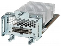
Customers have the option to install up to 4 GRWIC modules in the Cisco CGR 2010. CGR 2010 allows any combination of GRWIC modules to be populated in the 4 GRWIC slots on the router. The GRWIC SKUs in Table 10 below can be ordered with the router or as spares.

Cisco Connected Grid Router 2010

The Cisco Connected Grid Router (CGR) 2010 is a rugged router optimized for use in transmission & distribution (T&D) power substations. The Cisco CGR 2010 is designed specifically for substation networks to meet the harsh environments common in transmission & distribution substations. It is built upon the award winning Cisco Integrated Services Router (ISR) G2 portfolio, and provides the substation operator with the benefits of improved security, broadband connectivity, and network reliability. The CGR 2010 uses Cisco IOS software which is the operating system powering millions of Cisco routers deployed worldwide. Cisco IOS software delivers the benefits of integrated security for NERC/CIP compliance, quality of service, and network management to ensure integrity and priority of operational data and non-operational data communications.
The Cisco CGR 2010 builds on the best-in-class offering of the existing Cisco 2900 Series Integrated Services Router G2 (ISR G2) platforms. With embedded hardware encryption acceleration, optional firewall, and intrusion prevention, the CGR-2010 delivers integrated security to help utilities comply with cyber security requirements outlined in the North American Electric Reliability Corporation's (NERC) Critical Infrastructure Protection (CIP) mandates. In addition, the platform supports T1/E1 WAN interfaces with integrated CSU/DSU interfaces, synchronous & asynchronous serial RS-232 interfaces, copper and fiber Gigabit Ethernet.
Figure 1. Cisco connected Grid Router 2000 Series
Front side:
Cable side:
The CGR 2010 router can be ordered as a base system or as security bundled system. The only difference between the base system and the security bundle is the addition of Security License PAK, all other options remain the same and the configurations and options mentioned in this ordering guide remain the same for both systems.
The Cisco 2010 Connected Grid Router (CGR 2010) base system and security bundle ordering SKUs

Wednesday, October 20, 2010

Cisco IOS Software

Cisco IOS Software
CGR 2010 delivers innovative technologies running on industry-leading Cisco IOS Software. Developed for wide deployment in the world's most demanding, harsh environments, the CGR 2010 platform is supported on Cisco IOS Software release 15.1T. Release 15.1(1)T provides support for a comprehensive portfolio of Cisco technologies, including the functionality and features delivered in releases 12.4 and 12.4T. New innovations in 15.1(1)T span multiple technology areas, including security, high availability, IP Routing and Multicast, quality of service (QoS), Multiprotocol Label Switching (MPLS), VPNs, and embedded management.
Cisco IOS Software Licensing and Packaging
A single Cisco IOS Universal image encompassing all IOS technology feature sets is delivered with the platforms. You can enable advanced features by activating a software license on the Universal image. Technology packages and feature licenses, enabled through the Cisco software licensing infrastructure, simplify software delivery and decrease the operational costs of deploying new features.
Three major technology licenses are available on the CGR 2010 platform; you can activate the licenses through the Cisco software activation process identified  . The three licenses are as follows:
• IP Base: This technology package is available as default.
• Data
• Security (SEC) or Security with No Payload Encryption (SEC-NPE)

Cisco CGR 2010

Product Overview
The Cisco CGR 2010 builds upon the award winning Integrated Services Routers G2 (ISR G2) platforms to deliver best in class routing, security, management, and network intelligence. With embedded hardware encryption acceleration, optional firewall, and intrusion prevention, the CGR 2010 delivers integrated security to help utilities comply with cyber security requirements such as the North American Electric Reliability Corporation's (NERC) Critical Infrastructure Protection (CIP) mandates. In addition, the platform supports T1/E1 WAN interfaces with integrated CSU/DSU interfaces, synchronous & asynchronous serial CISCO2821-AA/K9 interfaces, copper and fiber Gigabit Ethernet.
Key Business Benefits
The CGR 2010 is designed for network security, scalability, durability, and investment protection. The modular architecture facilitates upgrades to your substation network without requiring a fork lift upgrade of the routing platform. New modules can be added over time as communications requirements change. Table 1 lists the business benefits of the CGR 2010.
Table 1. Key Business Benefits of the CGR 2010
Benefits
Description
Services integration
• The CGR 2010 offers integrated services including advanced data routing, firewall, traffic shaping, quality of service, & network segmentation
Ruggedized for substation compliance
• Compliant with IEEE1613 and IEC61850-3 substation standards for ruggedization
• Natural convection cooled with no moving parts or fans for maximum reliability
• Extended EMI and surge protection for protection in substation environments
Services on demand
• A single Cisco IOS Universal Software image is installed on each CGR 2010. The Universal image contains all of the Cisco IOS technology sets which can be activated with a software license. This allows your business to quickly deploy advanced features without downloading a new IOS image. Additionally, larger default memory is included to support the new capabilities.
Network management
• CiscoWorks LMS and Cisco Configuration Profession (CCP) network management tools to help utilities provision and diagnose network issues
• Embedded management tools capable of event detection and recovery offered directly in a Cisco IOS Software device. For more information, please see Tables 5 & 6 for details on Cisco network management solutions offered with the CGR 2010

Cisco CGR 2010

Networking Solutions and the Cisco CGR 2010: Substation Automation Example
Substation automation promises to bring more automation and intelligence to the power grid network to address a myriad of utility challenges. Utilities are focused on how to improve grid reliability, enhance network security to meet regulatory requirements, and reduce operational expenses. The Cisco Connected Grid Router & Switch offer utilities a rugged networking solution to enable reliable and secure two-way communication for substation automation. Figure 1 shows a converged end-to-end IP network from the data center to the home. The CGR 2010 and the CGR 2520 are deployed in both transmission and distribution substations. Networking these points of presence provide network operators with greater visibility into grid assets and help identify, isolate and restore outages more efficiently.
Figure . Places in the Network

Primary Cisco CGR 2010 features:

• Rugged industrial design and substation compliance with IEC-61850-3 and IEEE 1613 for utility substation environments
• Integrated security to help utilities address compliance with critical infrastructure protection mandates
• High availability design for maximum network up time and redundancy
• Network and device management tools for deployments, upgrades, and remote monitoring
• Advanced quality of service (QoS) C1861-SRST-F/K9 capabilities to support mission-critical substation communications such as SCADA (Supervisory Control and Data Acquisition)
Comprehensive network security features based on open standards
Figure 1. Cisco CGR 2010
Networking Solutions and the

Cell-Site Router Redundancy

Used in conjunction with Cisco MWR 1941-DC-A Mobile Wireless Edge Router, the Cisco T1/E1 RAN VWIC supports router redundancy at a cell site while sharing a single T1/E1 Abis/Iub and backhaul links to yield highly available RAN transport. A pair of Cisco MWR 1941-DC-A routers is deployed at the cell site, providing an active and standby router for redundancy. A failure of one Cisco MWR 1941-DC-A router, or a component of the router, causes the standby router to take over as the active router for the cell site. Each pair of Cisco MWR 1941-DC-A routers at the cell site is identical in hardware configuration, and connected to each other through the integrated 100BASE-T interfaces. The individual T1/E1 links to a Cisco MWR 1941-DC-A are cabled from a single T1/E1 termination block in the cell site, connecting to both the active and standby routers utilizing a Y-cable. The redundancy design to control the active/standby transitions of the router pair uses Hot Standby Router Protocol Plus (HSRP+) to control the relays on the Cisco T1/E1 RAN VWIC in each router, which ensures that the relays on the active router are closed and the relays on the standby router are open to avoid double termination of the T1/E1 links.
Depending on the Cisco MWR 1941-DC-A router implementation, the Cisco T1/E1 RAN VWIC can be used in a standalone router or in redundant Cisco MWR 1941-DC-A router configurations. For redundant configurations, a special Y-cable is required to connect the active and standby routers. The Y-cable provides a dual E1 or T1 PRI connection.
The specifications of the Y-cable are: CISCO1841-ADSLI
• Cisco T1/E1 RAN VWIC Y-cables should be made with four twisted-pair, shielded, 28-gauge cables.
• The cable length of each stub (from the RJ-48C connector to the junction point) should not exceed 3 inches (76 mm).
• The cable length from junction point to the patch panel is determined by the customer.
• All signals that propagate in the same direction must share the same twisted pair. For example, RX TIP and RX RING must form a single twisted pair.
• All unused twisted pairs should be cut flush on both ends of the cable. Any unused wire in a twisted pair where one wire is in use should be cut flush at both ends.