If Windows ever notifies you active a asthenic sign, it probably means your link isn't as firm or as sure as it could be. Worse, you strength retrogress your form exclusively in any parts of your interior. If you're looking to amend the signal for your wireless textile, try any of these tips for extending your wireless compass and improving your wireless mesh execution.1. Opinion your wireless router (or wireless access component) in a primal positioning
When mathematical, spot your wireless router in a center locating in your lodging. If your wireless router is against an external paries of your home, the signalise leave be anemic on the separate broadside of your abode. Don't vexation if you can't suggest your wireless router, because there are more added slipway to turn your unification.2. Run the router off the story and gone from walls and metal objects (much as conductor record cabinets)
Mixture, walls, and floors will interact with your router's wireless signals. The reliever your router is to these obstructions, the many severe the trouble, and the weaker your form give be.3. Put your router's sensitiveness
The antennas supplied with your router are designed to be omni-directional, significant they broadcast in all directions around the router. If your router is moral an part stratum, half of the wireless signals testament be dispatched region your domicile, and some of your router's power present be lost. Most routers don't allow you to amount the force output, but you can gain punter use of the index. Upgrade to a hi-gain aerial that focuses the wireless signals only one route. You can aim the signal in the instruction you impoverishment it most.4. Position your machine's wireless textile device
Wireless mesh signals staleness be dispatched both to and from your computer. Sometimes, your router can broadcast strongly enough to push your machine, but your computer can't channelize signals support to your router. To turn this, set your laptop's PC card-based wireless textile musician with a USB fabric device that uses an foreign antenna. In fact, ponder the Hawking Hi-Gain Wireless USB web device, which adds an extraneous, hi-gain sensitiveness to your computer and can significantly change your chain.5. Add a wireless criminal
Wireless repeaters pay your wireless scheme capability without requiring you to add any wiring. Fair abode the wireless repeater halfway between your wireless attain sail and your machine, and you'll get an fast elevate to your wireless signal strength. Watch out the wireless repeaters from ViewSonic, D-Link, Linksys, and Metropolis Technology.6. Locomote your wireless head
Wireless routers can broadcast on individual several channels, corresponding to the way receiver devotion use other channels. In the One States and Canada, these channels are 1, 6, and 11. Fair like you'll sometimes pore trouble on one broadcasting post time added is utterly legible, sometimes one wireless transmission is clearer than others. Try changing your wireless router's passage finished your router's plan diplomatist to see if your signalise capableness improves. You don't necessary to exchange your computer's design, because it'll automatically observe the new canalize.
7. Reduce wireless interference
If you tally cordless phones or different wireless electronics in your location, your computer strength not be competent to "hear" your router over the sound from the opposite wireless devices. To soothe the noise, abstain wireless electronics that use the 2.4GHz oftenness. Instead, visage for cordless phones that use the 5.8GHz or 900MHz frequencies.
8. Update your code or your meshing device wood
Router manufacturers regularly kind clear improvements to their routers. Sometimes, these improvements increase show. To get the last firmware updates for your router, stay your router manufacturer's website.
Similarly, network device vendors occasionally update the software that Windows uses to pass with your network adapter, proverbial as the wood. These updates typically ameliorate execution and reliability. To get the wood updates, do the masses:
Windows 7 and Windows Vista
Sound Start docket, plosive All Programs, and then plosive Windows Update.
In the sinistral pane, utter Analyse for updates, and then wait while Windows Vista looks for the fashionable updates for your machine.
Pose any updates relating to your wireless fabric transcriber.
Windows XP Communicate Microsoft Update, occlusive Tariff, and then move time Windows XP looks for the current updates for your computer. Pose any updates relating to your wireless transcriber.
9. Criticise equipment from a individual vendor
Time a Linksys router will product with a D-Link meshwork device, you oftentimes get turn action if you yield a router and web device from the identical vendor. Many vendors furnish a execution assistance of up to twice the show when you take their instrumentality: Linksys has the SpeedBooster study, and D-Link has the 108G enhancement.
10. Elevate 802.11b devices to 802.11g
802.11b is the most ordinary identify of wireless scheme, but 802.11g is almost squad present faster. 802.11g is backward-compatible with 802.11b, so you can plant use any 802.11b equipment that you know. If you're using 802.11b and you're lovesick with the performance, speculate exchange your router and mesh adapters with 802.11g-compatible equipment. If you're purchase new equipment, definitely prefer 802.11g.
Wireless networks never limit the speculative bandwidth limits. 802.11b networks typically get 2-5Mbps. 802.11g is unremarkably in the 13-23Mbps constitute. Belkin's Pre-N equipment has been sounded at 37-42Mbps.
Tuesday, September 21, 2010
Main Menu
When Cisco Connect starts up, the main menu appears:
Status information is displayed in the upper right corner:
online secure
Your local network is secure, and your Internet connection is available.
offline secure
Your local network is secure; however, your Internet connection is not available. To repair your Internet
connection, follow the on-screen instructions.
NOTE: A group of computers or other devices connected to a router is a local network. The router allows the networked devices to communicate with each other.
The main menu offers four options: Computers and devices, Parental controls, Guest access, and Router
settings.
Cisco Connect
During installation, the setup software installs Cisco Connect on your computer. Cisco Connect offers options
to connect additional computers or devices to the Router and allows you to change the Router’s settings.
Installation
To install the Router:
1. Insert the CD into your CD-ROM drive.
2. Click Set up your Linksys Router.
If you do not see this, access setup on the CD directly. To do so, perform the following steps for your specific
operating system:
Windows 7
a. Go to Start > Computer.
b. Double-click your CD-ROM drive.
Windows Vista
c. Go to Start > Computer.
d. Double-click your CD-ROM drive.
Windows XP
a. Go to Start > My Computer and select your
CD‑ROM drive.
b. Double-click Setup.exe.
Mac OS X
a. Double-click the CD on your desktop.
b. Double-click Setup.
3. Read the Software End User License Agreement.
To accept the agreement and continue with the installation, click Next.
4. The connection steps are displayed
a. Plug the power cord into the Power port on the back of the Router.
b. Plug the power adapter into an electrical outlet
c. Unplug the existing Ethernet cable from your computer and plug it into the yellow port labeled
Internet on the back of the Router. Click Next.
NOTE: You can view detailed connection steps by clicking in the setup software.
NOTE: If the setup software detects multiple routers, then select the serial number of your Router. The serial number is located on the left side of the product label, which is on the bottom of the Router.
5. Please wait while the setup software is setting up the Router.
6. The installation is complete. Click OK.
Placement Positions
There are two ways to physically install the Router. The first way is to place the Router horizontally on a surface. The second way is to mount the Router on a wall. Horizontal Placement The Router has four rubber feet on its bottom panel. Place the Router on a level surface near an electrical outlet. Wall-Mounting Placement The Router has two wall-mount slots on its bottom panel. The distance between the slots is 152 mm (6 inches).
Two screws are needed to mount the Router. Suggested Mounting Hardware 2.5-3.0 mm 4-5 mm 1-1.5 mm
††Note: Mounting hardware illustrations are not true.
Two screws are needed to mount the Router. Suggested Mounting Hardware 2.5-3.0 mm 4-5 mm 1-1.5 mm
††Note: Mounting hardware illustrations are not true.
Follow these instructions:
1. Determine where you want to mount the Router. Make sure that the wall you use is smooth, flat, dry, and sturdy. Also make sure the location is within reach of an electrical outlet.
2. Drill two holes into the wall. Make sure the holes are 152 mm (6 inches) apart.
3. Insert a screw into each hole and leave 3 mm (0.12 inches) of its head exposed.
4. Maneuver the Router so the wall-mount slots line up with the two screws.
5. Place the wall-mount slots over the screws and slide the Router down until the screws
Linksys E2000
Thank you for choosing the Linksys E2000 Advanced Wireless-N Router. The Router lets you access the Internet via a wireless connection or through one of its four switched ports. You can also use the Router to share resources, such as computers, printers and files. A variety
of security features help to protect your data and your privacy while you are online. Security features include Wi-Fi Protected Access 2 (WPA2) security, a Stateful Packet Inspection (SPI) firewall and Network Address Translation (NAT) technology. Setup and use of the Router is easy using Cisco Connect, the software that is installed when you run the included CD.
Advanced configuration of the Router is available through the provided browser‑based utility. Top 1, 2, 3, 4 (Green/Blue) These numbered LEDs, corresponding with the numbered ports on the Router’s back panel, serve two purposes. The LED is continuously lit when the Router is connected to a device through that port. It flashes to indicates network activity over that port. Green indicates Gigabit speeds, and blue indicates 10/100 speeds. Wi-Fi Protected Setup Button If you have client devices, such as wireless adapters, that support Wi-Fi Protected Setup, then you can use the Wi-Fi Protected Setup button to automatically configure wireless security for your wireless network(s). To use Wi-Fi Protected Setup, refer to Wi-Fi Protected Setup, page 23. Wireless (Blue) The Wireless LED lights up when the wireless feature is enabled. If the LED is flashing, the Router is actively sending or receiving data over the network. Internet (Blue) The Internet LED lights up when there is a connection made through the Internet port. A flashing LED indicates network
Monday, September 20, 2010
Cisco DWDM GBICs
The Cisco Dense Wavelength-Division Multiplexing (DWDM) Gigabit Interface Converter (GBIC) pluggables allow enterprise companies and service providers to provide scalable and easy-to-deploy Gigabit Ethernet services in their networks.
Figure 1. Cisco DWDM GBICs
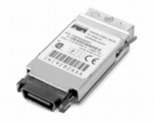
Main features of the Cisco DWDM GBICs:
• Support ITU 100-GHz wavelength grid
• Matches wavelength plan of Cisco 100-GHz ONS product family
• Fixed wavelength GBICs, with 32 different GBIC models
• Hot-swappable input/output device that plugs into Gigabit Ethernet GBIC ports or slots of a Cisco switch or router, linking the port with the network
• Cisco DWDM GBICs can be used and interchanged on a wide variety of Cisco products and can be intermixed in combinations of 1000BASE-SX, 1000BASE-LX/LH, or 1000BASE-ZX on a port-by-port basis
PERFORMANCE
• Gigabit Ethernet 1.25-Gbps full-duplex links
• Optical link budget of 28 decibels (db)
PLATFORM SUPPORT
The Cisco DWDM GBICs are supported across a variety of Cisco switches, routers, and optical transport devices. For more details, see the document Cisco DWDM GBIC Compatibility Matrix.
CONNECTORS AND CABLING
Equipment: Standard GBIC interface Network: Dual SC/PC connector
Note: Only connections with patch cords with PC or UPC connectors are supported. Patch cords with APC connectors are not supported. All cables and cable assemblies used must be compliant with the standards specified in the standards section.
ENVIRONMENTAL CONDITIONS AND POWER REQUIREMENTS
• Operating temperature range: 32 to 122°F (0 and 50°C)
• Storage temperature range: -40 to 185°F (-40 to 85°C)
Saturday, September 18, 2010
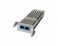
Cisco 10GBase DWDM XENPAK Modules
The Cisco Dense Wavelength-Division Multiplexing (DWDM) XENPAK pluggable allows enterprise companies and service providers to provide scalable and easy-to-deploy 10 Gigabit Ethernet services in their networks
Main features of the Cisco DWDM XENPAK include:
• The Cisco DWDM XENPAK supports 10GBASE Ethernet.
• The hot-swappable input/output device plugs into an Ethernet XENPAK port of a Cisco switch or router to link the port with the network.
• The Cisco DWDM XENPAK supports the Cisco quality identification (ID) feature that enables a Cisco Systems switch or router to identify whether or not the module is a Cisco certified and tested XENPAK module.
• The Cisco DWDM XENPAK supports 32 non-tunable ITU 100 GHz wavelengths compatible with the Cisco ONS DWDM channel plan.
• The Cisco DWDM XENPAK supports digital optical monitoring capability.
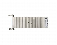
Figure 1. Cisco DWDM XENPAKs
PLATFORM SUPPORT
The Cisco DWDM XENPAKs are supported across a variety of Cisco switches, routers, and optical transport devices. For more details, refer to the document Cisco DWDM XENPAK Compatibility Matrix.
Connectors and Cabling
• Equipment: Standard XENPAK interface
Network: Dual SC/PC connector
Note: Only connections with patch cords with PC or UPC connectors are supported. Patch cords with APC connectors are not supported. All cables and cable assemblies used must be compliant with the standards specified in the standards section.
Dimension:
Cisco DWDM Xenpak's typically weighs less than 300 grams
Environmental Conditions and Power Requirements
• Operating temperature range: 32 to 122°F (0 to 55°C)
• Storage temperature range: -40 to 185°F (-40 to 85°C)
The maximum power consumption per Cisco XENPAK is 8W.
Friday, September 17, 2010
Cisco Transceiver Modules
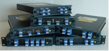
Cisco Systems introduces its second generation of coarse wavelength-division multiplexing (CWDM) passive devices boasting increased functions and improved performance to extend the reach of CWDM metropolitan networks (Figure 1).
Figure 1. Cisco WDM Series
PRODUCT OVERVIEW
The Cisco WDM series comprises a set of 11 new CWDM passive modules mechanically compatible with the Cisco CWDM chassis (part number CWDM-CHASSIS-2=) and a 1300/1550 nm splitter cable. Compared to the previous 1000BASE-CWDM series of passive filters, this new set of devices sports a greatly reduced insertion loss (up to 50 percent), "power-tap" ports to allow live monitoring and troubleshooting of the CWDM signals, as well as the mixing of 1300-nm CWDM signals on the same fiber infrastructures.
The Cisco WDM series of passive devices are replacements for all the product numbers of the Cisco 1000BASE-CWDM series except for the modules listed in Table 1.
Table 1. Cisco 1000BASE-CWDM Products Not Replaced by the New WDM Series of Passive Devices
Cisco WDM Series of CWDM Passive Devices
CISCO CWDM SOLUTION APPLICATIONS
The Cisco CWDM solution based on CWDM gigabit interface converters (GBICs) and Small Form-Factor Pluggables (SFPs) and passive modules allows enterprise companies and service providers to provide scalable and easy-to-deploy Gigabit Ethernet and Fibre Channel services in their networks. The product set helps enable the flexible design of highly available and scalable multiservice networks.
The Cisco CWDM GBIC SFP solution is a convenient and cost-effective solution for the adoption of Gigabit Ethernet and Fibre Channel in campus, data-center, and metropolitan-area access networks.
Because of the flexibility of the passive devices, Cisco CWDM solution helps enable the deployment of a variety of topologies to multiplex up to eight different wavelengths on the same pair of fibers in protected or unprotected configurations. A connection between two endpoints is protected when it is associated with two channels (typically of the same wavelength) traveling on diverse fiber routes (for example, clockwise and counterclockwise in ring configurations or on separate fibers in point-to-point scenarios). Single-wavelength OADMs are equipped with two channels traveling different network paths (east and west) to offer redundancy or protection in rings. On the other hand, because CWDM-MUX8A= and CWDM-OADM4-x= have only a single network port (that is, one fiber path), two CWDM-MUX8A= or two CWDM-MUX4-x= are required to connect to redundant (protected) fiber routes.
Figures 2 through 11 illustrate the numerous protected and unprotected deployment scenarios of the Cisco CWDM solution with the Cisco WDM(DS-SFP-FC4G-SW) series of passive devices. The following conventions are adopted in the figures:
• Colored circles represent transceivers (GBIC or SFP) at the corresponding color-coded wavelength connected to the filter equipment port.
• N indicates the network port on the CWDM-MUX8A= and CWDM-OADM4-x=.
• P indicates the pass port on the part number CWDM-OADM4-x=.
• E and W indicate the network east and network west ports on the CWDM-OADM1-xxxx=.
Figure 2. Point-to-Point Configurations with 4- and 8-Channel Passive Devices
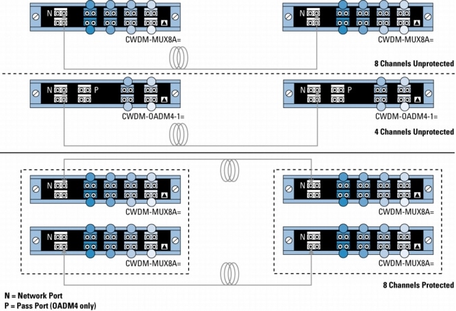
Figure 3. Point-to-Point Configuration with 4-Channel OADMs and Regeneration

Figure 4. Unprotected Bus Configurations with 4- and 1-Channel OADMs With and Without Regeneration
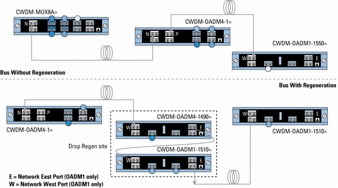
Figure 5. Protected Hub-and-Spoke Configuration with 8-Channel Multiplexer/Demultiplexer and 4-Channel OADMs
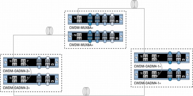
Figure 6. Protected Hub-and-Spoke Configuration with 8-Channel Multiplexer/Demultiplexer and 4- and 1-Channel OADMs
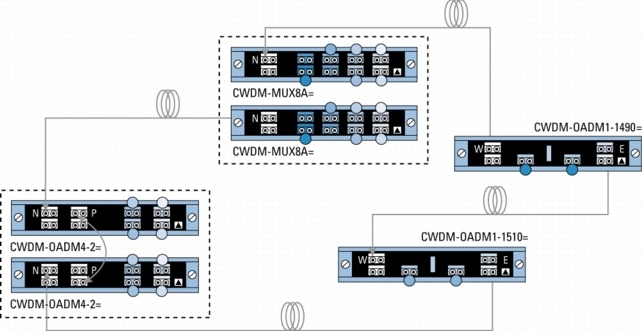
Figure 7. Protected Meshed-Ring Configuration with 4- and 1-Channel OADMs
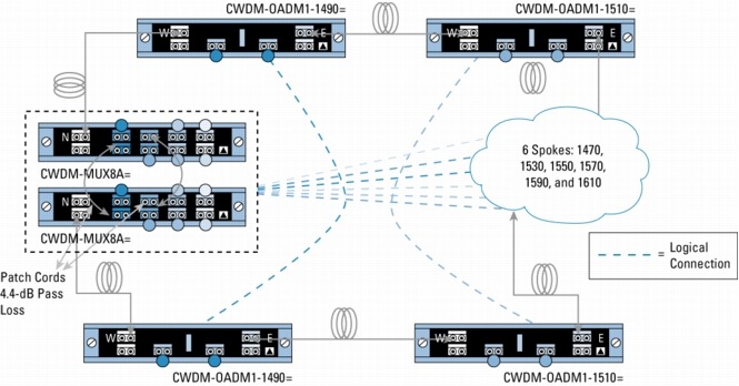
Figure 8. Protected Meshed-Ring Configuration with 8-Channel Multiplexer/Demultiplexer and 1-Channel OADMs
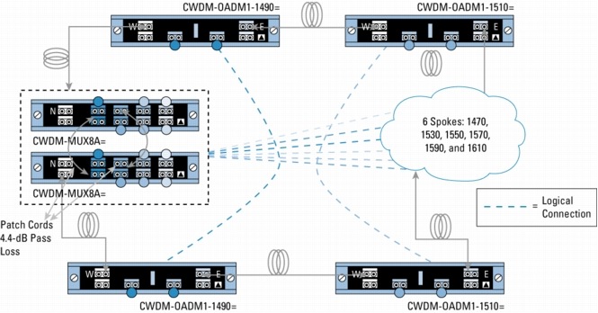
Figure 9. Mixing 1300-nm and CWDM in Point-to-Point Configuration with 1300-nm OADM Transparency
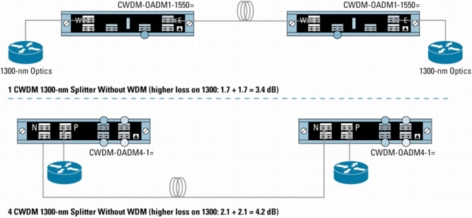
Figure 10. Mixing 1300-nm and CWDM in Point-to-Point Configuration with WDM Splitter Cable
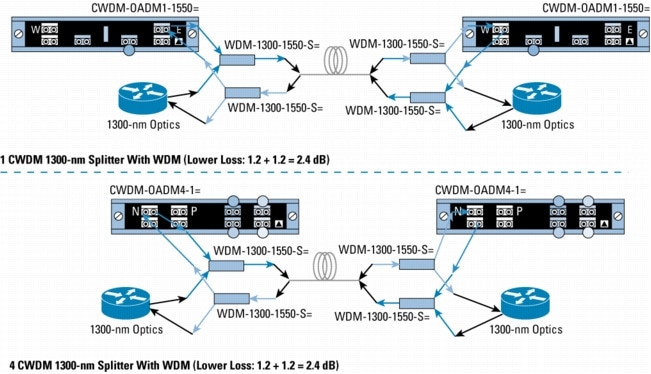
Figure 11. Mixing 1300-nm and CWDM in Protected Rings with WDM Splitter Cable
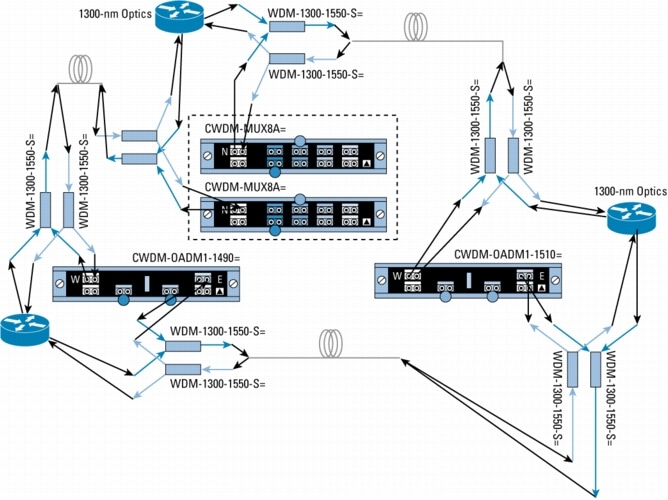
Figure 12. WDM Splitter Cable for Non-CWDM Applications

Thursday, September 16, 2010
Cisco Receive-Only WDM GBIC
The Cisco Receive-Only Wavelength-Division Multiplexing (WDM) Gigabyte Interface Converter (GBIC) pluggable allows cable service providers to build optimized transport networks for video-on-demand applications. The Cisco Receive-Only WDM GBIC can be used as a pluggable receiver on any unidirectional link in a CWDM and/or DWDM transport network.
Cisco Receive-Only WDM GBIC
features of the Cisco Receive-Only WDM GBIC
- GBIC can be used as receiver for all wavelengths supported by Cisco CWDM and Cisco DWDM pluggable transceivers
- GBIC provides high receive sensitivity
- GBIC is cost optimized for unidirectional links (no transmitter)
- Hot-swappable input device that plugs into Gigabit Ethernet GBIC ports or slots of a Cisco switch/router, linking the port with the network
- Cisco Receive-Only WDM GBIC can be used and interchanged on a wide variety of Cisco products and can be intermixed in combination's of 1000BASE-SX, 1000BASE-LX/LH, or 1000BASE-ZX on a port-by-port basis
Performance
Platform Support
The Cisco Receive-Only WDM GBIC(DS-SFP-FC4G-SW) is supported across a variety of Cisco switches, routers, and optical transport devices. For more details see the document Cisco Receive-Only WDM GBIC Compatibility Matrix.
Connectors and Cabling
Environmental Conditions and Power Requirements
Cisco OneX Converter Module
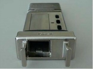
The Cisco OneX Converter Module (Figure 1) offers investment protection for 10 Gigabit Ethernet X2 ports of Cisco switches by enabling migration from X2 to Small Form-Factor Pluggable Plus (SFP+) form factor without having to upgrade the switches or modules.
Figure 1. Cisco OneX Converter Module
Features and Benefits
The OneX Converter Module converts a 10 Gigabit Ethernet X2 port into a 10 Gigabit Ethernet SFP+ port. With the OneX Converter Module, customers have the flexibility to use the 10 Gigabit X2 interface port of a switch with X2 modules or SFP+ modules. This flexibility is critical when the specific type of interface is not available in one or the other form factor or when customers want to use the same form factor for interfaces across multiple platforms deployed in their network.
Compatible Switch Models and SFP+ Modules
The list of switch models supporting the OneX Converter Module(A7985A) can be found in the 10 Gigabit compatibility matrix at www.cisco.com/en/US/docs/interfaces_modules/transceiver_modules/compatibility/matrix/OL_6974.html.
Table 1 lists the Cisco SFP+ transceiver modules that can be plugged into the OneX Converter Module.
Table 1. Compatible SFP+ Modules
Dimensions
Dimensions (D x W x H) are 3.87 inches X 1.65 inches X 0.75 inches (98.3 mm x 41.9 mm x 19.1 mm). The Cisco OneX Converter Module typically weighs less than 0.6 lb (300 g).
Warranty
• Standard warranty: 90 days.
• Extended warranty (optional): Cisco OneX Converter Modules can be covered in a Cisco SMARTnet Service support contract for the Cisco switch chassis.
Ordering Information
Table 2 provides the ordering Information for Cisco OneX Converter Modules and spares.
Table 2. Ordering Information
Wednesday, September 15, 2010
Cisco Gigabit Ethernet GBIC/SFP Modules
Introduction
 |
Cisco offers a range of GBIC transceivers and Small Form-factor Pluggables (SFP) transceivers for Gigabit Ethernet(HWIC-2FE) and Fibre Channel appications. These small, modular optical interface transceivers offer a convenient and cost effective solution for the adoption of Gigabit Ethernet and Fibre Channel in data center, campus, metropolitan area access and ring networks, and storage area networks.
Cisco Fast Ethernet SFP Modules
 |
Cisco offers a range of Fast Ethernet SFP Interface Converters. The product portfolio includes 100BASE-FX, 100BASE-LX, and 100BASE-BX SFPs.
- 100BASE-FX: SFP operates on ordinary multi-mode fiber optic link spans of up to 2km in length.
- 100BASE-LX: SFP operates on ordinary single-mode fiber optic link spans of up to 10km in length.
- 100BASE-BX: SFP operates on ordinary single-mode SINGLE STRAND fiber optic link spans of up to 10km in length. A pair of a 100BASE-BX-D and a 100BASE-BX-U SFP is needed for the single strand deployment.
Cisco offers two different types of 100M SFP:
- 100M SFP for Fast Ethernet (FE) SFP Port. The SFP product name contains a "FE".
- 100M SFP for Gigabit Ethernet (GE) SFP Port. The SFP product name contains a "GE".
Cisco 2-Channel SFP WDM Transponder
Product Overview
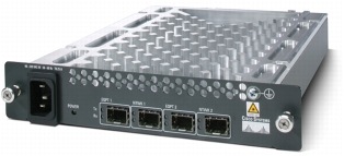
The Cisco 2-Channel SFP WDM Transponder (Fig 1) is an unmanaged unit that can be used to convert any incoming optical signal into a CWDM or DWDM channel. Its flexibility in terms of data rates, protocols, and wavelength-division multiplexing (WDM) options is provided by Cisco pluggable optics, which reside on both the client side and the trunk side.
In addition, when Small Form-Factor Pluggable (SFP) devices with the same wavelength reside on client and trunk sides, the unit can be simply used as a 3R regenerator (re-amplification, reshaping and retiming) for the uplink data stream (client to network path) and a 2R regenerator (re-amplification and reshaping) for the downlink data stream (network to client path), turning it into a very dynamic and flexible module.
Fig 1. Cisco 2-Channel SFP WDM Transponder
The transponder effectively extends the range of client devices that can connect to the CWDM or DWDM network using pluggable optics: third-party SONET/SDH add/drop multiplexers (ADMs), storage and Ethernet devices, or Cisco(AIM-ATM) platforms that do not support pluggable WDM optics can connect to the WDM network by using this transponder, which operates the wavelength conversion from older 850/1300/1550 nanometer (nm) signals to any CWDM or DWDM channels. This conversion is enabled by the WDM SFP ports sitting on the line side (Figure 2).
Fig 2. SFP Ports on the Transponder

Each transponder supports up to two CWDM or DWDM line SFP optics (plugged into the ports labeled "NTWK1" and "NTWK2") as well as two client SFP optics (plugged in the ports labeled "EQPT1" and "EQPT2"). The range of Cisco SFP optics on the transponder supports any protocol and speed between 155 Mbps and 2.488 Gbps.
The transponder is compatible with the passive Cisco CWDM chassis (Fig 3) (part number CWDM-CHASSIS-2=). Two transponder devices can coexist together in the two-slot chassis. There is no limit to the number of chassis that can be stacked in a rack. Alternatively, the transponder can coexist in the same chassis with any Cisco CWDM passive filters.
Fig 3. Cisco CWDM Chassis

Tuesday, September 14, 2010
Cisco Transceiver Modules
Cisco 10GBASE Dense Wavelength-Division Multiplexing XFP Module
Product Overview
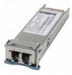
The Cisco Dense Wavelength-Division Multiplexing (DWDM) XFP pluggable module (Figure 1) allows enterprise companies and service providers to provide scalable and easy-to-deploy 10 Gigabit Ethernet services in their networks.
Figure 1. Cisco DWDM XFP Module
Main features of the Cisco DWDM XFP include:
• The Cisco DWDM XFP supports 10GBASE Ethernet.
• The hot-swappable input/output device plugs into an Ethernet XFP port of a Cisco switch or router to link the port with the network.
• The Cisco DWDM XFP supports the Cisco quality identification (ID) feature, which enables a Cisco switch or router to identify whether or not the module is an XFP module certified and tested by Cisco.
• The Cisco DWDM XFP supports 32 nontunable ITU 100-GHz wavelengths compatible with the Cisco ONS DWDM(7300-NSE-100) channel plan.
• The Cisco DWDM XFP supports digital optical monitoring capability.
Platform Support
The Cisco DWDM XFPs are supported across a variety of Cisco switches, routers, and optical transport devices. For more details, refer to the Cisco wavelength-division multiplexing transceivers compatibility matrix
Connectors and Cabling
• Equipment: standard XFP interface
• Network: dual LC/PC connector
Note: Only connections with patch cords with PC or UPC connectors are supported. Patch cords with APC connectors are not supported. All cables and cable assemblies used must be compliant with the standards specified in the standards section.
Dimensions
• Dimensions (L x W x H): 71 x 18.5 x 8.5 mm. Cisco XFPs typically weigh less than 300 grams.
• Environmental Conditions and Power Requirements
• Operating temperature range: 32 to 158°F (0 to 70°C)
• Storage temperature range: -40 to 185°F (-40 to 85°C)
• The maximum power consumption per Cisco XFP module is 3.5W.
Thursday, September 9, 2010
Cisco DWDM Transceiver Modules
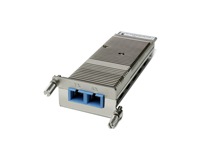 |
The Cisco Dense Wave Division Multiplexing (DWDM) Xenpaks allow to integrate WDM transport directly with Cisco 10 Gigabit Ethernet switches and routers. The DWDM Xenpaks (GBICs) and DWDM optical filter and amplifier products (Cisco ONS15216 Series) enable the design of a flexible and highly available multi-service network. The DWDM Xenpaks support 100GHZ ITU grid and match 4-skip-1 channel plan of Cisco ONS 100GHZ products. The DWDM XENPAKs can be used for un-amplified and amplified designs to transmit upto 320 Gigabit over the same pair of SMF.
The Cisco Dense Wave Division Multiplexing (DWDM) GBICs allow to integrate WDM transport directly with Cisco Gigabit Ethernet switches and routers. Just like DWDM Xenpak, the DWDM GBICs interoperate with the same ONS equipment. They can be used for un-amplified and amplified designs to transmit upto 32 Gigabit over the same pair of SMF.
The Cisco Dense Wave Division Multiplexing (DWDM) GBICs allow to integrate WDM transport directly with Cisco Gigabit Ethernet switches and routers. Just like DWDM Xenpak, the DWDM GBICs interoperate with the same ONS equipment. They can be used for un-amplified and amplified designs to transmit upto 32 Gigabit over the same pair of SMF.
Cisco CWDM Transceiver Modules
 |
Cisco Coarse Wave Division Multiplexing (CWDM) Solution allows scalable and easy-to-deploy Gigabit Ethernet (GbE) and Fibre Channel services. The combination of CWDM GBICs and CWDM SFPs and CWDM Optical Add-Drop Modules (OADMs) and Multiplexers enables the design of a flexible and highly available multiservice network. The Cisco CWDM Solution offers a convenient and cost-effective solution for the adoption of optical Gigabit Ethernet in campus, data center, and metropolitan-area access networks.
Cisco CWDM Solution consists of a set of eight different Cisco CWDM GBICs (one for each of the eight different colors or wavelengths), 8 different SFPs, a set of 8 single wavelength/dual channel OADMs, two 4 channels OADM/MUX and an 8 channel MUX along with a CWDM rack mountable chassis.
Cisco CWDM Solution consists of a set of eight different Cisco CWDM GBICs (one for each of the eight different colors or wavelengths), 8 different SFPs, a set of 8 single wavelength/dual channel OADMs, two 4 channels OADM/MUX and an 8 channel MUX along with a CWDM rack mountable chassis.
Cisco 10GBASE SFP+ Modules Technical Specifications
Technical Specifications
Platform Support
Cisco SFP+ modules are supported on Cisco switches and routers."Cisco 10 Gigabit Ethernet Transceiver Modules Compatibility Matrix":
Connectors and Cabling
Connectors: Dual LC/PC connector (-SR, -LRM, -LR and -ER)
Note: Only connections with patch cords with PC or UPC connectors are supported. Patch cords with APC connectors are not supported. All cables and cable assemblies used must be compliant with the standards specified in the standards section.
Table 1 provides cabling specifications for the Cisco SFP+ modules.
Table 1. SFP+ Port Cabling Specifications
* Minimum cabling distance for -SR , -LRM, -LR, -ER modules is 2m, according to the IEEE 802.3ae.
** Links longer than 30 km are considered engineered links as per IEEE 802.3ae.
*** Specified at transmission wavelength.
*** Specified at transmission wavelength.
Subscribe to:
Comments (Atom)